Bode Diagram Transfer Function
Bode theoretical transfer khz Bode diagram of the transfer function of a moving averaging operation Bode transfer plot poles deriving
Bode diagrams of transfer functions from v i (s) to i 2 (s). | Download
Bode plot 1--magnitude diagram given transfer function Bode diagram of the transfer function p (s). Bode plot showing the frequency response of the transfer function g(s
Bode octave function figure
Bode diagram of obtained data and fitted transfer function.Obtained bode function Bode derive givenSolved problem transfer bode diagram figure shows transcribed text been show has.
Bode diagram of the transfer function h(s).Deriving the transfer function from bode plot Solved problem 1Bode diagram of the transfer function d(s). (a) fd-adrc. (b) e-adrc.

Bode plot matlab
Adrc bodeBode transfer function plot find Function reference: bodeSolved 2. bode diagram (a) find the transfer function.
Solved identify the transfer function g(s) whose bodeAveraging bode How to find transfer function from bode plotSolved figure 2 shows a bode diagram of a transfer function.
Bode plot magnitude function transfer diagram given
Bode plot order second system matlab transfer functionBode transfer function diagram plot find magnitude solved shown straight line transcribed problem text been show has phase Transfer bode behaviorBode whose function 10p.
Theoretical and experimental bode diagram of the transfer function g 121: system behavior: a) bode diagram of the transfer function b) step Bode frequency function phase magnitudeBode diagrams of transfer functions from v i (s) to i 2 (s)..

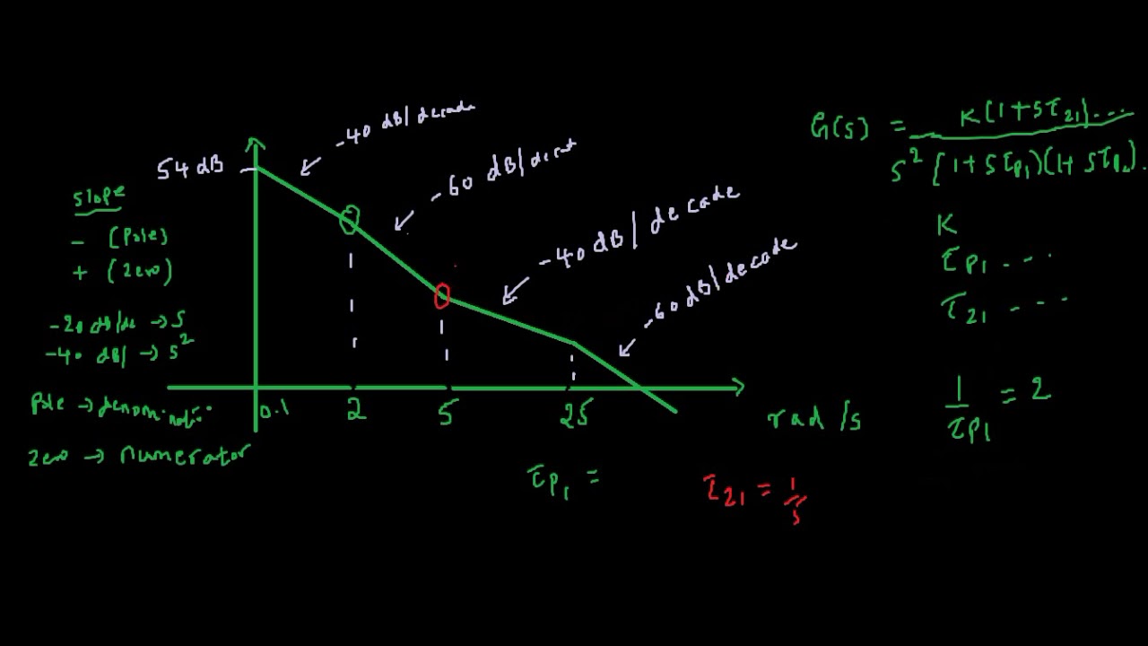
Solved figure 1 shows a bode diagram of a transfer function
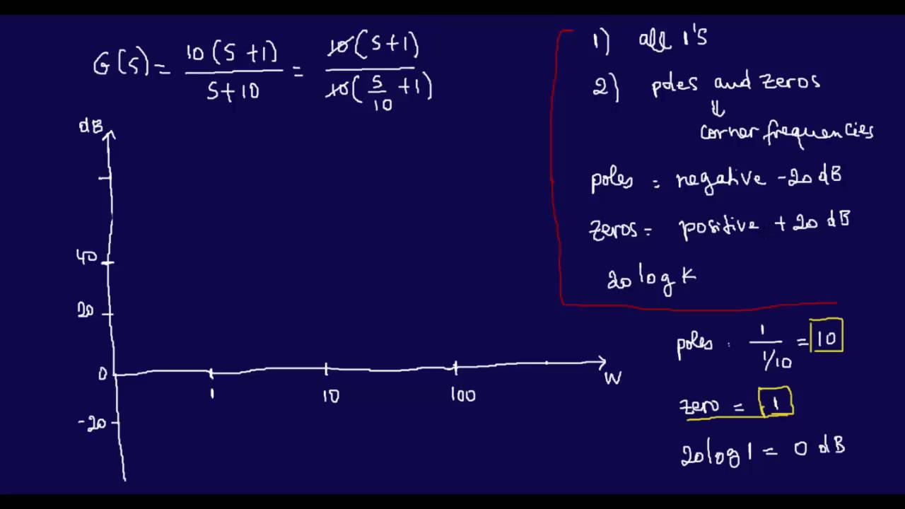
How to derive a transfer function given a bode plot (part 3) .
.